The milling mechanism of the large circular seam welding machine mainly performs the milling groove on the large cylindrical workpiece. Because the welding system has high requirements on the quality of the groove, the positioning accuracy of the milling mechanism in the direction of the bed is also required. At the same time, the milling mechanism is only a part of the bed. If the accuracy of the rack and the performance of the geared motor are simply improved, the cost of the whole equipment will be increased. Therefore, it is necessary to design a transmission system that is both economical and ensures positioning accuracy.
1. Milling mechanism transmission design
As shown in the drawing, the milling mechanism transmission device is composed of a hand wheel, a compression spring, a stroke switch, a coupling, a safety pin, a reduction motor, a gear, a key, a rack, a linear guide slider and a linear guide. The rack and the linear guide are mounted on the bed body, and the milling mechanism drives the gear to mesh with the rack by the reduction motor as the initial positioning. When the adjustment is performed accurately, the reducer is engaged with the rack by the hand wheel. In order to reduce friction, the milling device is mounted on a high precision linear guide. When manually fine-tuning, the hand wheel is coupled to the shaft end of the reduction motor through the universal joint to realize the movement, that is, the guide rail slider is coupled with the milling mechanism through the screw, and the gear and the output shaft of the reduction motor are connected by a key, and the gland is pressed. When the milling mechanism is working, the braking action is completed by the cylinder pressing device and the transmission device on the milling mechanism.
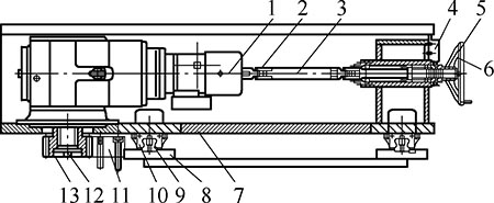
Milling mechanism transmission
1. Geared motor 2. Safety pin 3. Coupling 4. Travel switch 5. Compression spring 6. Handwheel 7. Milling mechanism 8. Bed 9. Linear guide 10. Linear guide slider 11. Rack 12. Key 13. gear
2. Working principle
The geared motor on the milling mechanism drives the gear to mesh with the rack on the bed, and drives the milling mechanism to move along the bed on the linear guide. After determining the milling position, it will automatically switch to manual. The fine adjustment of the feeding device is realized by rotating the hand wheel. Firstly, the hand wheel is pushed axially to compress the spring, the stroke switch is activated, and the motor is powered off by the PLC control signal, and the manual operation is performed to prevent the motor from rotating during the manual operation. personnel. After the spring is compressed, the two separate plum-shaped couplings are pushed to mesh, and the rotating hand wheel drives the double-output shaft reducer to rotate through the universal joint, and the gear of the output shaft of the reduction motor and the rack rotates, which drives the milling mechanism along the The bed moves in the direction of the bed.
A safety pin is installed on the universal joint. When the milling mechanism is blocked and overloaded, the safety pin is broken to protect the input shaft of the tail end of the reduction motor. After the precise adjustment position is completed, the hand wheel is released, the hand wheel moves in the opposite direction under the action of the spring force, the plum-shaped coupling is disengaged, the stroke switch is reset, and the electric control device receives the signal, and the deceleration motor is energized to restore the initial state. When the reduction motor is working, since the two parts of the plum-shaped coupling are separated, the rotating hand wheel does not follow the rotation, thereby ensuring the safety of the operator. After the positioning is completed, in order to prevent the milling force from pushing the milling mechanism mounted on the linear guide slider, the transmission motor brakes, and the compression cylinder on the milling mechanism works to fix the milling mechanism together.
3. Conclusion
The design comprehensively considers the working principle and manufacturing cost of the milling mechanism transmission device in the large welding system, the structure is simple, the operation and maintenance are convenient, and the working precision of the milling mechanism can be well ensured. For large-scale welding system milling mechanism transmissions, compared with the design of fully automatic control, the manufacturing cost is low, the cycle is short, and the positioning accuracy is ensured; compared with the completely manual control design, in the case of a slight increase in manufacturing cost, Work efficiency has been significantly improved while reducing work intensity.
references:
[1] Wen Bangyu. Mechanical Design Handbook [M]. 5th edition. Beijing: Mechanical Industry Press, 2010.
(Received date)
The sole of shoes is Pu Rubber Sole which the structure is combined with PU middle sole and rubber outer sole.
It is more wearproof than PU- PU Sole Safety Shoes, and has the anti - corrosion property of rubber.
And it is lighter,soft and cheaper than the Rubber Sole shoes. So it excellent performance of PU and rubber.
PU Rubber Sole
Work Safety Boots,Climbing Safety Boots,Fashion Safety Shoe,Pu Rubber Sole
Greateagle Safety Products Co., Ltd. , https://www.greateaglesafety.com