Medium frequency induction furnace optical coil protection system device
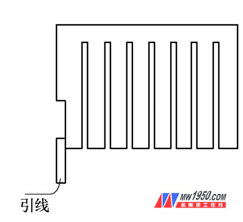
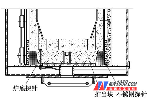
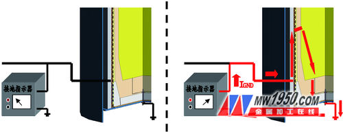
The medium frequency induction furnace lining is made up of various refractory materials and is knotted in a certain proportion. In the long-term smelting production process, the molten iron continuously washes the lining of the furnace. After a period of time, the molten iron will seep out from the cracks in the eroded lining wall. If it reaches a high temperature of thousands of degrees, it will cause extreme poles to the induction coil and the yoke. Great damage can cause an explosion in serious cases and a personal safety crisis. Therefore, the setting of the leak alarm system is particularly important. This paper summarizes several forms, principles, advantages and disadvantages of leaking furnace alarms, and on this basis introduces an advanced and novel alarm device - optical coil protection system for peer reference. First, the alarm system For a long time, there is no clear definition of the specific classification of the alarm system. This paper combines the application and research of the melting furnace for many years, and the production practice in the enterprise, and classifies the alarm system into the following five categories (see Figure 1). Figure 1 Alarm System Classification Contact type The alarm system is a more traditional form, which in principle achieves the purpose of controlling the alarm by measuring the resistance and current of the lining. Six to seven stainless steel wires are placed in contact with the molten iron at the bottom of the lining. As the first electrode, a stainless steel sheet is disposed as a second electrode between the lining and the side wall of the induction coil. In normal use, the reading of the ammeter can reflect the degree of scouring of the lining. As the lining is washed, the resistance of the lining is gradually reduced. In the production process, both the lining and the asbestos board have large insulation resistance, and the ammeter reading value is small. Once the lining is severely scoured or the lining is broken due to improper operation, the lining resistance will drop drastically, and the ammeter reading in the circuit will rise sharply, up to several hundred milliamperes. The system can give an alarm by contacting the stainless steel piece before the molten iron contacts the coil. The contact alarm system is consistent in the design of the first electrode, but the second electrode is in different forms, including a stainless steel plate structure and an alarm-piece and mica integrated structure. 5. Coil 6. Stainless steel plate 7. Asbestos cloth (1) Stainless steel plate structure This structure was widely used in the 1980s and 1990s. The original structure in the 1980s consisted of placing multiple layers of glass cloth, asbestos cloth, asbestos board and mica board from the surface of the coil, followed by stainless steel, asbestos, asbestos, etc. (see Figure 2). In the 1990s, with the development and improvement of technology, the furnace wall structure from the induction coil to the inside was coil slurry, mica, second electrode, asbestos cloth and furnace lining (see Figure 3). In the furnace, a layer of about 0.5mm thick stainless steel plate is added, and the lead wire is made and wrapped with mica board insulation tape. The stainless steel plate is laid by the lap joint method. In order to prevent breakage or disengagement, the wire is connected by stainless steel wire. . When laying, use the expansion ring to make the stainless steel plate close to the inner wall of the induction coil to ensure the laying is smooth. In order to make the stainless steel plate as the second electrode easy to bend, so that it can be laid around the furnace wall, the whole stainless steel plate needs to be evenly cut into a curtain shape (see Fig. 4), which can better meet the use requirements. 4. Mica paper 5. Slurry 6. Coil The advantage of this structure is that the coil can be better protected when the furnace is leaked. After the 1990s, due to the addition of a layer of slurry, the damage to the coil during the furnace removal (especially manual demolition) is reduced, and There is a certain slope when preparing the slurry, which is beneficial to the mechanical automatic furnace operation. The disadvantage is that the design is more complicated, the furnace is more complicated, the stainless steel plate needs several expansion processes to achieve, the cost is high, and it is necessary to join layer by layer. The furnace materials are used for a long time. At the same time, special attention should be paid to the quality of the connection and extraction of the second-level alarm line (see Figure 4) to prevent the alarm from malfunctioning. Figure 4 stainless steel grid (2) Alarm piece and mica integrated structure The structure is basically the same as the stainless steel plate structure, except that the second electrode replaces the stainless steel plate with a 0.1 mm thick non-magnetic stainless steel piece, and the stainless steel piece is uniformly adhered to the mica board, the alarm piece Forms an integrated structure with mica. The longitudinally discharged stainless steel sheets are separated by a distance of 5 to 10 cm, and a stainless steel sheet is laterally cross-crossed at the intermediate position to ensure good contact with the longitudinal stainless steel sheets (see Fig. 5). Figure 5 stainless steel sheet Although the contact alarm method is effective, it can play the role of pre-alarm in most cases, improving the safety of use, but the reliability is not high, and false alarms and alarm failures often occur, leading to early shutdown and scrapping. The condition of the lining affects normal production. Among them, the second electrode lead-out line is easy to break, which is a major cause of alarm failure. 2. Inductive (1) Principle The basic principle of the furnace protection device is to add a DC voltage between the ungrounded induction coil and the ground, and continuously measure and display the leakage current through a milliampere meter. If the leakage current exceeds the set value, the induction coil, the molten iron, and the grounding probe form a complete closed loop, that is, an audible and visual alarm is issued, and the electric furnace power supply is stopped, thereby achieving the purpose of leakage protection. Here, the grounding probe can be regarded as the first electrode, and the leakage current in the grounding electrode of the electric furnace is actually generated by applying the intermediate frequency voltage on the induction coil to the equivalent resistance of the lining. As the lining wall is continuously thinned, etc. The effect impedance also becomes smaller, and the leakage current is continuously increased, so the induction coil can be regarded as the second electrode in the entire system. (2) Specific form The alarm system has a simple structure, and the power supply unit is provided with a ground leakage detector for detecting low grounding resistance in the electrical system, which is essential for safe melting and heat preservation operations, and includes a grounding detector module connected to the power supply. , as well as ground leakage detector probes, indicator lights, milliampere meters, etc. When the furnace is being blown, make sure that the grounding probe at the bottom of the furnace is in contact with the charge or in contact with the conductive crucible (see Figure 6). The bottom probe is made of non-magnetic stainless steel wire with a diameter of 1 to 2 mm (see Figure 7 for details). ), introduced through the small hole in the bottom of the furnace. In addition, it is necessary to lay a layer of mica paper between the coil slurry and the lining to reduce the friction when the lining is pushed out. Figure 6 Part of the bottom of the furnace Figure 7 probe form (3) Alarm condition The grounding probe cooperates with the grounding detector module (see Figure 8). When any abnormal grounding phenomenon is detected in the induction coil, the power supply is automatically cut off. The leakage alarm signal occurs when the coil and grounding resistance are less than 1kΩ. The necessary condition for the alarm is that the grounding probe must be in contact with the molten iron, and there is an applied voltage of 60V on the coil, that is, an alarm occurs when the leakage current exceeds 60 mA (see Figure 9), which often includes the following three conditions: 1 metal liquid seepage The furnace is lined to the coil. 2 furnace lining is too humid. 3 furnace or power system has low ground resistance. Figure 8 Normal state Figure 9 Alarm status Such an inductive alarm mode is simple in structure, easy to build a furnace, and requires careful design and mature technology to support it. It is a relatively advanced form of alarm, which is mostly adopted by imported equipment manufacturers, and domestic manufacturers are less involved. For more information, please see Metalworking (Hot Processing), Issue 3, 2013. GUANGZHOU SUNPLUS TECHNOLOGY CO.,LTD , https://www.sunplussandpaper.com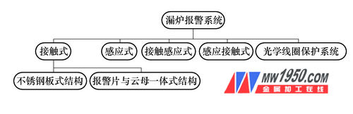
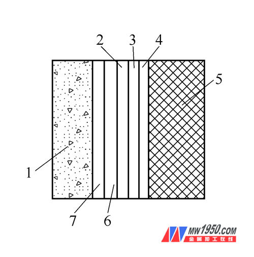
1. lining 2. asbestos board 3. mica board 4. glass cloth 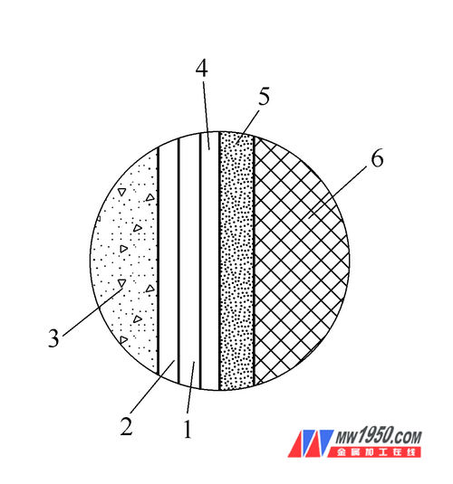
1. Stainless steel plate 2. Asbestos cloth 3. Furnace lining