Research on Test Method of General Automatic Detection System for Military Shortwave Radio Field
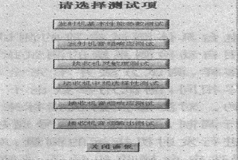
The radio test is to measure the radio input and output and some key indicators and analyze the results to determine whether the radio is working properly. According to the actual application of the military radio test, especially in the field conditions, the rapid and accurate detection of the radio, and then determine the working state of the radio, the timely replacement of the radio fault module is critical. This paper mainly studies the radio test methods, including radio test indicators, test connection relationships and test procedures. 1 System Introduction Figure 1 Schematic diagram of the system of radio detection equipment The signal input/output interface on the object to be tested is connected to the detecting device through the adapter, and the 220 V (50 Hz) AC power supply supplies power to the detecting device, and the integrated power supply supplies power to the object to be tested via the signal conditioning switching unit, and is operated by the operator. The software performs diagnostic tests. It has many functions such as function detection, fault diagnosis, general measurement and maintenance data inquiry; it can quickly isolate the faults of each unit and combination to the replaceable unit; the coverage rate and diagnostic accuracy are ≥90%. 2 Test indicators and methods 2.1 Main test indicators For short-wave radio stations, the test indicators that can be realized by the automatic detection system are: basic performance parameters of the transmitter, including RF output power, peak point frequency, bandwidth, carrier suppression, etc.; transmitter audio response; receiver sensitivity Receiver IF selectivity; receiver audio response; receiver audio output. The test item selection interface is shown in Figure 2. Figure 2 test project selection interface Privacy Garden Steel Fence,Security System Steel Fence,Spear Top Steel Fence Anping Deming Metal Net Co., Ltd. , http://www.hswiremeshfence.com
The military short-wave radio universal detection equipment integrates equipment detection, fault diagnosis and information inquiry. It is developed on the basis of a hardware platform composed of PXI bus system and a software platform composed of Lab Windows/CVI. The detection system consists of two parts: test hardware and test software. The test hardware platform consists of PXI bus chassis, RF switch (PXI-2593), audio analyzer (PXI-4461), signal generator (PXI-5421), oscilloscope (PXI-5112), MIX card and computer. The test software is mainly developed by NI Labwindows/CVI7.1. The signal generator and modulation mediation software analysis package are combined with the analog RF signal input and output. The oscilloscope and spectrum software analysis package are combined to calculate various detection parameters. The database uses MS SQLServer 2000. Save the data and generate a report document using MS Word 2003. In the process of processing and calculating various feature values, the following two data analysis processing packages are mainly used:
(1) Spectrum analysis toolkit;
(2) Signal modulation and demodulation kit.
The block diagram of the military short-wave radio universal detection equipment system is shown in Figure 1. 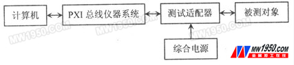
There are a variety of radios, and different types of radios have different performance indicators. In the actual test environment, especially under field conditions, it is unrealistic and unnecessary to achieve measurement of all performance indicators. In fact, only need to select a key indicator that reflects the working state of the radio, and then judge the radio working status according to the obtained information, and replace the fault function module. Since military radio stations are mostly short-wave and ultra-short-wave radio stations, the test methods for the main performance indicators of these two radio stations are mainly studied. The test of a short-wave radio station is taken as an example to illustrate the implementation of the test method.