Control example of machining quality of gearbox gear (2)
After the OP30 hobbing, the gear precision is also required to be detected. The main test items are: Previous page next page 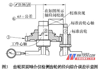
Maximum tooth direction error f H β : Right flank: ( 0 ±10) mm ; Left flank: ( 0 ±10) mm.
Maximum tooth profile direction error f H α : Right flank: ( 0 ±10) mm ; Left flank: ( 0 ±10) mm.
Maximum tooth direction direction error variation Wf H β : right tooth surface: 15 mm; left tooth surface: 15 mm.
Maximum tooth shape direction error variation Wf H α : right tooth surface: 14 mm; left tooth surface: 14 mm.
Total tooth error F β : right flank: 22 mm; left flank: 22 mm.
Total tooth profile error F α : right flank: 22 mm; left flank: 22 mm.
The average adjacent pitch error f um : 6mm.
Pitch cumulative error F p : 58 mm.
The detection of gear accuracy is mainly carried out on the M&M gear measuring center. When measuring, the gear cone faces down and the clamping can be positioned with the expandable mandrel. The parameters of the programming input are: the rotation direction is left, the right tooth surface is a non-working surface, the left tooth surface is a working surface, the minimum tooth width is 15.4 mm, and the maximum value of the chamfer is 0.
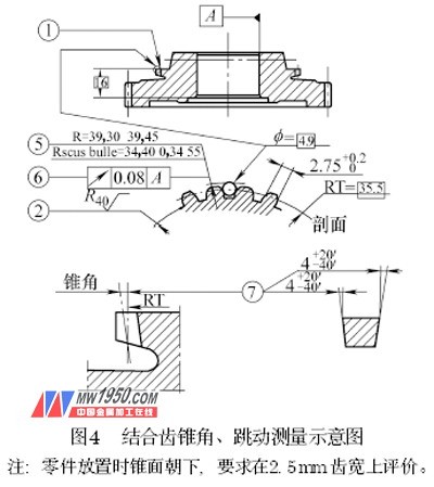
After the 4OP40 is inserted into the tooth, the inspection process diagram is shown in Fig. 4. The measurement method of the cone angle 7 is to convert the cone angle into the maximum tooth direction direction error and measure it on the MM gear measurement center. The converted values ​​are as follows: maximum tooth direction error f H β ; right flank: -0. 146~ -0. 189 mm; left flank: 0. 146~0. 189mm.