Research on CAD System of 3D Fixture Based on SolidWorks
Next page
The current Lanwei software's parametric design, assembly simulation, interference checking and finite element analysis provide powerful technical support for computer-aided fixture design, which makes the fixture design under the three-dimensional platform become a research hotspot.
1. Three-dimensional CAFD system structure system
The machine tool fixture is composed of several basic units such as a mountain positioning component (or component), a tool setting component, a guiding component (or component), a clamping component (or component), and a clip. The design features of the machine tool fixture are mainly reflected in: the various components of the fixture can be designed separately. Compared with the general product design, the reconstruction of the fixture design is still relatively strong. Therefore, the CAFD system mainly completes the following aspects of design: positioning, tool setting, guiding, clamping, and clamping specifics. Each design should include program determination and component selection. Under the three-dimensional design platform, the process of computer-aided fixture design generally goes through three stages: conceptual design, technical design and fine design.
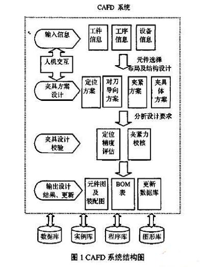
The fixture design process requires not only a large amount of data on part design, process and machining, but also a wealth of domain knowledge and design experience. According to the fixture design requirements and system function analysis, the 3D CAFD system is divided into the following functional parts: information input function part, auxiliary program design function part, design verification function part and result output function part. The input information includes: workpiece information, process information, equipment information; the fixture design needs to design the positioning scheme, the tool guiding scheme, the clamping scheme, the clip specific scheme; the fixture design verification is mainly the specified bit accuracy evaluation and clamping The check of the force; the final process is to output the design results, including the component diagram, the assembly diagram BOM, and update the database. The system structure is shown in Figure 1.