Multi-station progressive die design for terminal block (2)
Figure 3 mold structure diagram 1. Upper template 2. Guide sleeve 3. Guide post 4. Punch fixing plate 5. Rubber block 6. Cutting punch Since the precision of the parts is not high, the whole mold adopts the double guide column and the guide sleeve guiding structure arranged on the rear side for convenient operation. When the mold is working, the cut strip is first fed from the right end of the mold to the guide ruler 17. The initial position is determined by visual inspection, the mold is descended, and the strip is punched out of the pre-formed hole at the first station; the strip continues Feeding, in the second station, the pre-made hole punched out is positioned by the cylindrical pin 12; the mold is again lowered, and the intermediate rectangular hole for breaking the two parts is punched out; as the strip reaches the third station, the strip is punched Bending prefabricated holes; the strips are fed to the 4th station to complete the bending and rounding of the round holes; the 5th station cuts the strips and completes the processing of the finished parts of the two parts. According to this cycle, the mold will reach two pieces each time. (2) Design points All punching punches, bending punches, and through-hole punches are formed by wire cutting, which adopts a straight-through type, and is fixed to the punch fixing plate 4 by riveting due to small structural size or irregular shape. The guide rod 17 is used for lateral positioning, manual feeding, and the floating guide pin 11 is used for lifting and floating feeding. The initial positioning of the mold is positioned by the operator's eye, and after the strip is fed in, the subsequent station is positioned by the cylindrical pin 12. All the punches are in sliding engagement with the stripper plate 7 to protect the punch and prevent breakage. Since the workpiece is to be bent and rounded at the 4th station, in order to ensure the smooth and smooth feeding of the strip, in addition to the installation of multiple floating guide pins in the mold, especially in the turning and bending compound The corresponding lower die of position 4 is designed with a flip hole discharge block 22 and a curved discharge block 19, so that the press elastic buffer can first push the turned hole and the bent portion out of the mold cavity through the ejector pins 20, 21, thereby avoiding When the strip is fed, there may be a stagnation due to insufficient topping force of the floating guide pin 11. The main parts such as the punch fixing plate 4, the discharge plate 7, and the die 15 are all cut by wire. 4. Conclusion After the design and manufacture of the multi-station progressive die, the test mode was carried out, and the dimensions of the processed parts met the product requirements. The design of the multi-station progressive die combines the process, which is beneficial to mass production. Compared with the original processing technology, the production efficiency of the enterprise is improved, and the working conditions of the operator are improved. The manufactured progressive die is used in production and processing for more than one year. The product quality is stable and the mold works well. For more articles, please refer to "Metal Processing" Cold Processing 2008 No. 1 Previous page Perforated Non-woven Fabric,Perforated Nonwoven Fabrics,Perforated Nonwoven Tablecloth non woven fabric protection cover Co., Ltd. , http://www.nonwfabric.com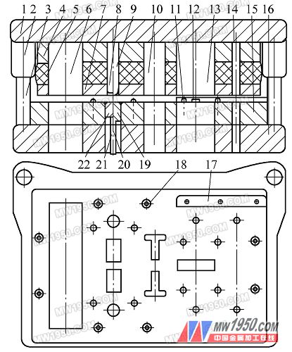
7. Unloading plate 8. Turning hole punch 9. Bending punch 10. Punching punch 11. Floating guide pin
12. Cylindrical pin 13. Rectangular hole punch 14. Round hole punch 15. Die 3. Lower template
17. Guide rod 18. Screw 19. Bending discharge block 20, 21. Plunger 22. Turning hole discharge block