[
Huaqiang Security Network News ]
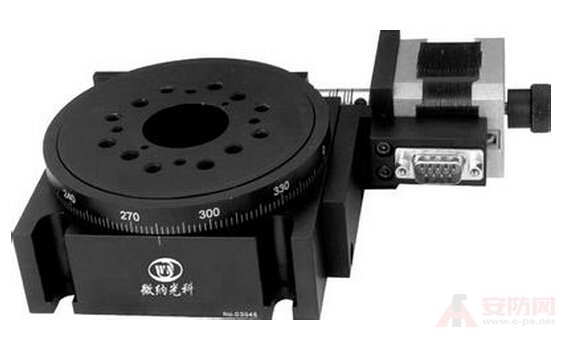
Optical encoder classification and selection
Encoder Encoder is a kind of sensor (Sensor), which is mainly used to detect the speed, position, angle, distance or counting of mechanical motion. In addition to industrial machinery, many motor controls such as servo motor and BLDC servo motor are used. An encoder is required for the motor controller to detect the commutation, speed and position, so the application range is quite wide. According to the detection principle, the encoder can be divided into optical, magnetic, inductive and capacitive. According to its scale method and signal output form, it is divided into incremental encoder and absolute encoder. The photoelectric encoder realizes the displacement-digital conversion by the principle of grating diffraction. It has been applied to machine tools and computing instruments since the 1950s. Due to its simple structure, high measurement accuracy and long life, it has been valued and promoted at home and abroad. Positioning, speed, length, acceleration, vibration and other aspects have been widely used.
a. Incremental encoder features:
When the incremental encoder rotates the shaft, there is a corresponding pulse output, and the starting point of the counting is arbitrarily set, which can realize unlimited accumulation and measurement of multiple circles. A single rotation of the encoder shaft outputs a fixed pulse, the number of pulses being determined by the number of lines of the encoder grating. When you need to increase the resolution, you can use the A and B signals with a phase difference of 90 degrees to multiply or replace the high-resolution encoder.
b. Absolute encoder features
Absolute encoders have a code output corresponding to the position, usually a binary code or a BCD code. From the change in the number of codes, the position of the forward and reverse directions and the displacement can be discriminated. The absolute zero code can also be used for the power failure position memory. Absolute encoders have a measurement range of 0-360 degrees.
Incremental rotary encoder
The incremental encoder provides a certain number of pulses per revolution of the shaft. Periodic measurements or pulse counts per unit time can be used to measure the speed of movement. If the number of pulses is accumulated after a reference point, the calculated value represents the parameter of the angle of rotation or stroke. The difference between the output pulses of the two-channel encoder is 90o. The electronic device that receives the pulse can receive the rotation sensing signal of the shaft, so it can be used to realize bidirectional positioning control; in addition, the three-channel incremental rotary encoder generates a pulse called a zero signal every revolution.
Incremental Absolute Rotary Encoder The absolute encoder provides a unique coded digital value for each axis position. Especially in positioning control applications, the absolute encoder reduces the computational task of the electronic receiving device, thus eliminating the need for complicated and expensive input devices: and, when the machine is plugged in with power or power failure, the power is turned on, You need to go back to the location reference point to take advantage of the current position value.
The single-turn absolute encoder subdivides the axis into a specified number of measurement steps with a maximum resolution of 13 bits, which means that the maximum distinguishable 8192 positions + multi-turn absolute encoder can not only measure the angle in one revolution. Displacement, and fortunately, J uses a multi-step gear to measure the number of turns. The number of turns in multiple turns is 12 bits, which means that a maximum of 4096 turns can be identified. The total resolution can reach 25 bits or 33,554,432 measurement steps. The parallel absolute value rotary encoder transmits position values ​​to the estimation electronics for parallel transmission over several cables.
Incremental → Absolute Encoder
Rotating the incremental value encoder outputs a pulse when rotating, and its position is calculated by the counting device. When the encoder is not moving or power is off, the internal memory of the counting device is used to remember the position. In this way, when the power is off, the encoder can't have any movement. When the caller works, the encoder can not interrupt and lose the pulse during the output pulse. Otherwise, the zero point calculated and memorized by the counting device will be offset, and this The amount of offset is unknown, and only the wrong result will be known.
The solution is to increase the reference point, and the encoder corrects the reference position into the memory position of the counting device every time the encoder passes the reference point. Before the reference point, the accuracy of the position cannot be guaranteed. In the industrial control, there are methods such as finding a reference point for each operation, and starting to change the zero.
Such a method is troublesome for some industrial control projects, and even does not allow booting to change to zero (it is necessary to know the exact position after booting), and some working conditions do not allow the use of interference due to interference, so there is an absolute encoder. Appearance.
There are many optical channel engraving lines on the optical encoder of the absolute value rotary encoder. Each line is arranged in 2 lines, 4 lines, 8 lines, 16 lines... in this way, so that every position of the encoder By reading the pass and dark of each reticle, a set of unique binary codes (Gray code) from the zeroth power of 2 to the n-1 power of 2 is obtained, which is called n-bit absolute coding. Device. Such an encoder is determined by the mechanical position of the optical code disc. It is not affected by power outages and interference. Since each position of the absolute value encoder determined by the mechanical position is unique, it does not need to be memorized, and there is no need to find a reference point. And don't have to count all the time, when you need to know the location, and when to read its location. In this way, the anti-interference characteristics of the encoder and the reliability of the data are greatly improved.
From single-turn absolute encoders to multi-turn absolute encoders
The single-turn absolute encoder is used to measure the scribe lines of the photoelectric encoder in rotation to obtain a unique code. When the rotation exceeds 360 degrees, the code returns to the origin, so that the principle of absolute coding is not met. The encoder can only be used for measurements within a range of 360 degrees of rotation, called a single-turn absolute encoder. To measure a range of more than 360 degrees of rotation, a multi-turn absolute encoder is used.
The encoder manufacturer uses the principle of the watch gear mechanism. When the center code wheel rotates, another set of code wheels (or sets of gears, multiple sets of code disks) is driven by the gear, and the number of turns is increased on the basis of the single-turn coding. Encoding to expand the measuring range of the encoder, such an absolute encoder is called a multi-turn absolute encoder, which is also uniquely unique for each position code without memory.
Another advantage of the multi-turn encoder is that due to the large measurement range, the actual use is often richer, so that it is not necessary to find a zero point during installation, and an intermediate position is used as a starting point, which greatly simplifies the difficulty of installation and debugging.
Absolute encoder signal output
The absolute encoder signal output has parallel output, serial output, bus type output, and variable output integrated output. The single-turn low-digit encoder is generally output with parallel signals, while the high-order and multi-turn encoder output signals are used. No parallel signal (multiple parallel signal cables, easy to be erroneous and easy to be damaged), generally serial or bus type output. Among them, the serial most commonly used is the clock synchronous serial signal (SSI); the bus type is the most commonly used PROFIBUS-DP type, and the other is DeviceNet, CAN, Interbus, CC-link, etc.; the integrated output is easy to use, but The precision is sacrificed.
A cold applied self adhesive aluminium backed flashing in roll form.
USES
_Window and door openings (headers, sills,jambs, thresholds, nailing flanges)
_Deck-to-wall intersections
_ Corner boards
_Wall-to-wall tie-ins
_Foundation sill plates
_Sheathing panel seams
_Under stucco finishes
_Car`s insulation
_ Roof detail areas
_ Gutters
_ Mobile home repair
_Other building joints.
_Exposed pipelines protection.

Waterproof Aluminium Foil Tape
Waterproof Aluminium Foil Tape,Aluminum Foil Tape,Cold Applied Tape,Aluminum Flashing Butyl Tape
Jining Qiangke Pipe Anticorrosion Materials CO.,Ltd , https://www.pipe-wrap-tape.com